| Pin | Function |
|---|---|
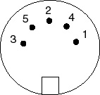
| 1 | COM |
| 2 | N/C |
| 3 | +5V |
| 4 | -5V |
| 5 | N/C |
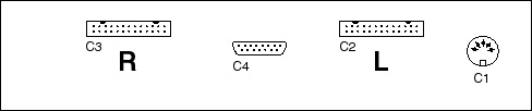
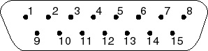
View facing the mating end of the connector
| L-Preamplifier (C2) | R-Preamplifier (C3) | ||||||||||||||||||||||||||||||||||||||||||||||||||||||||||||||||||||||||||||||||||||||||||||||||||||||||||||
|---|---|---|---|---|---|---|---|---|---|---|---|---|---|---|---|---|---|---|---|---|---|---|---|---|---|---|---|---|---|---|---|---|---|---|---|---|---|---|---|---|---|---|---|---|---|---|---|---|---|---|---|---|---|---|---|---|---|---|---|---|---|---|---|---|---|---|---|---|---|---|---|---|---|---|---|---|---|---|---|---|---|---|---|---|---|---|---|---|---|---|---|---|---|---|---|---|---|---|---|---|---|---|---|---|---|---|---|---|---|
|
|
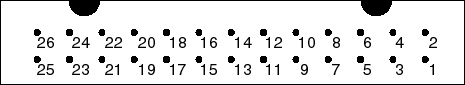
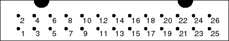
Notes: the Bits C(MSB), B, and A set the counter/setting for each amplifier channel. Hence if the voltages on Connector C2 pins 6, 5, and 4 are HIGH, LOW, and LOW (respectively) then Amplifier E is set to 4.
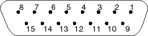
View facing the mating end of the connector
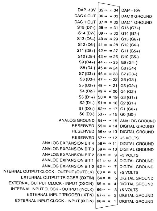
| Pin | Function |
|---|---|
| 1 | Select Channel, Bit C (MSB), to DAP Digital Output Bit 12 (DO12) |
| 2 | Select Channel, Bit B, to DAP Digital Output Bit 13 (DO13) |
| 3 | Select Channel, Bit A (LSB), to DAP Digital Output Bit 14 (DO14) |
| 4 | Advance Counter/Setting for Selected Channel, to DAP Digital Output Bit 15 (DO15) |
| 5 | Read Channel Setting Bit C (MSB), to DAP Digital Input Bit 6 (DI6) |
| 6 | Read Channel Setting Bit B, to DAP Digital Input Bit 7 (DI7) |
| 7 | Read Channel Setting Bit A (LSB), to DAP Digital Input Bit 8 (DI8) |
| Read Channel Setting | Channel Selected |
|---|---|
| (Bit C|Bit B| BitA) | |
| 0|0|0 | Channel A |
| 0|0|1 | Channel B |
| 0|1|0 | Channel C |
| 0|1|1 | Channel D |
| 1|0|0 | Channel E |
| 1|0|1 | Channel F |
| 1|1|0 | Channel G |
| 1|1|1 | Channel H |